Proposal for Aircraft Service Life Extensions Part 4: NDT and Experimental Testing Methods
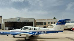
The center of my research on the potential for service life limit extensions for the Piper PA-44-180 SEMINOLE aircraft’s wing, wing carry-through and their attaching structure will consist of several rounds of testing. This article will explore the process and methodology for the proposed tests and experiments.
Before testing begins, there will be a rigorous inspection of the aircraft’s system to determine what forms of testing, including non-destructive testing (NDT), will be most efficient. This will outline the scope of the procedure, defining all parts of the structure to be tested, the appropriate NDT methods and additional information, such as exceptions for specific parts and inaccessible areas of the aircraft assemblies.
My team will develop a comprehensive system inspection to ensure the proper testing of structural elements requiring NDT acceptance. This process involves conducting inspections at every stage of the process and creating a list of all such components.
NDT Testing on the Piper PA-44-180 SEMINOLE
The proposed NDT inspection procedure for the SEMINOLE aircraft will focus solely on using inspection results to extend the service life of aircraft.
In this study, testing parts that have experienced mechanical damage involves analyzing the dimensions and predicting the remaining service life based on the current strength of the parts.
Structure and system engineers are tasked with evaluating main and secondary structure items. When completed in the past, it was found that not every structural item requires specific actions for extending its lifespan.
For instance, attachment structure components are typically created to withstand static stress conditions, impacts from crashes and maneuver accelerations, and stiffness criteria. The design process for the Piper SEMINOLE ensures that the equipment can withstand typical aircraft lifting and flight loads. However, the operational loading conditions of the aircraft vary over time, such as when an aircraft’s weight increases.
NDT Techniques and Methods
The proposed experiment uses various NDT techniques, methods and equipment for inspecting the wing, wing carry-through and their attaching structure.
These include:
Visual control (VC)
All parts will undergo visual inspection using tools like a 10x glass magnifier and a 100x optical microscope. These devices help to evaluate the depth of corrosion in areas where it has been detected and to forecast the depth of future corrosion that’s likely to occur.
Endoscope visual inspection (EVI)
Optical devices play a crucial role in detecting surface flaws effectively and determining the exact position and dimensions of defects. An endoscope makes it simple to locate cracks and identify areas of corrosion.
A wireless video endoscope is designed for examining automotive and aeronautical assemblies in hard-to-reach areas that require accurate visualization. The device only needs a tiny opening for the probe to enter, and—with wireless transmission—it allows for real-time viewing on a high-quality TFT display.
These endoscopes record video and images, providing a thorough examination of unreachable spaces and allowing staff to analyze them on a display or computer. The video endoscope can also connect to a screen to display the image on a bigger scale, and the pictures or videos collected can be saved to the SD card for later examination on a computer.
The team will use endoscope testing to evaluate all hard-to-reach locations, like the inner wing sections (including integral fuel tanks and void spaces behind the rear spar) and fittings attached to the main spar. The main objective of these inspections is to identify hidden defects and corrosion that can only be accessed through small openings using advanced technology.
Dye penetrant inspection (PI)
Penetrant inspection enhances the visibility of discontinuities against their background. This is achieved by using a liquid with strong penetrating capabilities that infiltrates the surface openings of the discontinuity.
A collection of penetrant fluids is used to identify surface imperfections in metallic materials composed of either ferrous or nonferrous alloys. First, the surface being inspected must be thoroughly cleaned to remove any sealants, compounds or anticorrosion coatings. This involves using solvent, cleaner and developer.
Once applied to the inspected surface, the penetrant fills the openings of any discontinuities and remains lodged within the cracks. After the treatment, any excess penetrant is removed, and a developer is applied. The developer draws out the penetrant from the material's cracks, leaving a red contrast visible against a white surface. Alternatively, the defects could be seen in fluorescence when illuminated with black ultraviolet light.
The procedure will use dye penetrant inspection on the wing to identify any potential surface defects or cracks.
Eddy current inspection (ECI)
The eddy current defectoscope, along with its probe, is designed for the accurate inspection and assessment of metal products composed of both ferromagnetic and non-ferromagnetic alloys, particularly in aircraft structural components and assemblies during their operational life.
This device can identify surface cracks and other defects, even on surfaces that are coated with non-conductive materials. It utilizes parametric probes that operate within a frequency range of 0.8 to 2 MHz.
Various factors influence the sensitivity of a defectoscope, including the type of probe used, the depth and volume of the defect, the direction in which the defect propagates, the nature of the defect, the conductivity of the material and the other physical or mechanical properties of the material being inspected.
Our team will conduct eddy current inspection on all primary attachment points—including the connections between the wings and fuselage, wing skin rivets and bulkheads—to identify any cracks and surface imperfections. This method is effective in detecting surface cracks, pits, subsurface cracks and corrosion on inner surfaces.
Ultrasonic inspection (UI)
Ultrasonic inspection is an NDT technique that uses sound waves traveling through the material to identify defects. My proposed research will use a defectoscope to complete the UI portion of testing.
The defectoscope is designed to ultrasonically detect defects and measure thickness. It features internal memory that allows for the archiving of data in two display formats, “A” scan and “B” scan, along with parameter settings and inspection outcomes.
This ultrasonic inspection method is applicable to materials that have anti-corrosive, non-conductive protection films. The defectoscope is compatible with a variety of probes operating within a frequency range of 0.8 to 15 MHz, depending on specific inspection requirements. In areas where corrosion is identified through visual inspection, it is essential to determine the depth of the corrosion, for which our team will use a defectoscope.
The sound waves that flow through the specimen can be represented visually on a Cathode Ray Tube (CRT), a Liquid Crystal Display (LCD) computer program or through video/camera technology. The resulting indications of both the front and back surfaces, as well as internal and external conditions, appear as vertical signals on the screen or nodes of data in the computer test program.
Ultrasonic inspection is particularly effective in identifying flaws that create reflective interfaces. This helps to uncover surface and subsurface discontinuities, including cracks, shrinkage cavities, bursts, flakes, pores, delamination and porosity. It is also used to measure material thickness and to inspect bonded structures for bonding voids.
In this experiment, ultrasonic inspection will be conducted to assess the remaining material thickness beneath any layers of corrosion and to measure the thickness of the corrosion itself.
Experimental and Computational Testing Methods
A series of experimental tests will also aid the research aimed at extending the operational lifespan of SEMINOLE aircraft structures. These tests will use original components from aircraft manufactured over 20 years ago, specifically from the initial phase of serial production for this aircraft model.
The testing will involve static loads and cyclic loads to simulate several thousand flight hours. The experiments will be conducted using a servo-hydraulic MTS system, specifically designed for static testing.
The fatigue testing of the aircraft bulkhead, specifically at the main wing fuselage joint of the SEMINOLE aircraft, will occur under loading spectra that’s experimentally determined during flight. This fatigue test will be executed utilizing a servo hydraulic MTS system and will simulate the equivalent of 5,000 flight hours. If no initial cracks are observed in the overall structure, this will confirm its residual life for an additional 5,000 flight hours.
Through experimental testing, I hope to show that the primary structural components of this aircraft maintain their mechanical properties even after more than 20 years of operation.
This is also the goal for the structural elements tested with load cycles. To assess the residual life of critical aircraft structural components, we’ll use computational methods. These methods integrate Finite Element Methods (FEM) for stress analysis with local software designed for initial fatigue life estimations.
FEM is recognized for its effectiveness in solving differential equations pertinent to engineering and mathematical modeling, with common applications in structural analysis, heat transfer, fluid dynamics, mass transport and electromagnetic potential.
In the next and final installment of this series, I’ll discuss how to analyze the results of the tests outlined in this article. I’ll also offer key considerations and potential conclusions for the experiment that offer insight into the value and plausibility of the research.
To review my concluding article, proceed to:
If you missed the first three parts of this series, you can find them here:
About the Author

