Technology-forward engineering firms have been using three-dimensional (3D) mapping for years to support the planning, design and data management of aviation projects, such runway mapping. But while their peers were utilizing this technology, it wasn’t until recently that the benefits of 3D mapping technology were recognized by the airfield electrical industry.
As airports continually expand to meet the demands of the growing travel population, the electrical and lighting infrastructure has to keep pace to ensure safety and reliability. By incorporating 3D mapping tools into a project, teams not only have a two-dimensional (2D) representation of each circuit and airfield lighting component, but also an additional 3D representation of the system for better visualization.
Recently, a groundbreaking use of 3D mapping for an airport’s electrical system occurred at Hartsfield-Jackson International Airport (ATL). Not only is ATL the world’s busiest airport for the past 18 years, but it is also the most illuminated, housing one of the most extensive airfield lighting systems. With more than 20,000 lights, 700 guidance signs, 600 manholes and 800 miles of cable, the resulting map is quite complex. To meet the demands of the increase in passengers over the years, significant airport expansion has occurred, including upgrades and growth to the airfield lighting system. These upgrades added a substantial number of electrical wires, manholes and other system parts below ground, which occupy the same space in electrical manholes as live, dead or abandoned wires.
Understanding the challenges ahead, ATL relied on its partners at AIS, an Atlanta-based joint venture team that brings together the expertise of Pond, Michael Baker International and CERM, to develop a solution that accurately documents the airfield lighting system. Ultimately, the findings could be applied to maintaining the existing electrical system while developing designs for future airfield construction improvement activities.
To accomplish the project’s goals, a unique solution was developed that utilizes 3D mapping to show and visualize the major parts of the airfield lighting system. Using this technology, the 3D map shows users an accurate and realistic representation of the major parts of the airfield lighting system. For something as complex as the airfield lighting system, this makes it easier for users to obtain information that they need from the as-built.
The resulting 3D map for ATL allows airport personnel to easily identify what is in each manhole and conduit. With such an expansive airfield lighting system, electrical wires—including not only live wires, but dead or abandoned ones as well—tend to get tangled in the ducts and manholes, which makes troubleshooting a circuit very difficult. In an airport environment where seemingly small delays can have a ripple effect on flight departure times, providing a simple and visually-conducive solution for maintenance crews working on electrical repairs is essential. By creating an accurate as-built of the information along with a 3D representation, the airport will now save time and manpower diagnosing airfield lighting problems.
In the ATL project, some of the electrical manhole ports do not have ducts coming from them, depicted as an empty duct that can be used for other circuits. This helps electrical crews performing manhole cleanup because circuits that are in a full conduit can be moved to an empty conduit. Prior to utilizing 3D mapping, this type of analysis was impossible. In the 3D map, the size of conduit is also shown. Most of the conduit on the airfield is either two-inches or four-inches, as depicted in the model below.
Figure 1: 3D model of conduit and manhole
Manhole butterfly layouts were created to depict what circuits are in each manhole and duct. This was used to create the unique 3D models of the manholes. Using AutoCAD Utility Design, each duct was drawn in 3D, then each circuit was routed through the exact duct that is out in the field. This was the first step in creating a 3D map of the entire airfield lighting system. In the case of ATL, there are some manholes with as many as 16 ducts coming from the manhole, so having things in 3D helps visualize what is leaving the manhole and in the conduit. Each circuit was drawn into the ducts as depicted in the field.
Figure 2: Circuit information shown with manhole
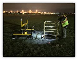
Figure 3: Field data collection for manhole butterfly layouts
Three-dimensional mapping also has the unmatched ability to highlight a single circuit. With circuits going all over the airfield, being able to highlight a single circuit helps save time and effort when troubleshooting an issue with a circuit. Knowing the exact path a circuit takes through an expansive airfield significantly speeds up the repair process.
Following the mapping phase of the project is a cleanup project where abandoned and dead wires will be removed in an effort to clean up the worst manholes, using a re-numbering scheme for all the circuits on the airfield. By having an accurate 3D map, the project can be more efficient in choosing which manholes to clean up and where the majority of the dead and abandoned wires are in the duct banks.
Intelligent Way to Save Time and Money
Three-dimensional mapping for airfield lighting systems is an intelligent solution capable of providing cost and time savings to airport management. With a detailed 3D map of the electrical wires across an entire airport on hand, maintenance and airport personnel can have a true picture of what is going on the with airfield lighting system, which is beneficial for both immediate repairs and future improvements.
Since the 3D map is built upon the 2D map, it offers smart functionality for personnel with the ability to hover over a numbered manhole on the map to see the exact circuits in the duct and corresponding duct number. By utilizing this technology, airports achieve a number of benefits:
1. Maintenance can quickly and easily view which wires in a duct or manhole are dead, abandoned or live. This makes the repair and improvement process not only simpler, but safer as well.
2. Reduction in the number of flight delays. By making repairs and maintenance more efficient, taxiways and runways do not need to be shut down for very long.
3. Improved time/cost savings for future airfield improvement projects. By having an accurate as-built paired with a detailed 3D map of the entire airfield lighting system, improvement projects can be more detailed and accurate in scope.
By not having to hunt down as-built drawings from the past 20-30 years, users can pull up the model and find out exactly what circuits and duct banks are entering and exiting the project limits. The 3D map gives the airport a more realistic and accurate model of all the wires in the airfield electrical system.
Challenges to Overcome
While 3D mapping has proven useful for modeling airfield lighting systems, especially at ATL, the technology still presents some drawbacks.
For one, and as is the case when adopting any new technology, to most effectively utilize an emerging platform, training must be in place to ensure proper adoption and use. As schedules are often crowded as is, making the time for additional training can prove challenging. And as the technology is still in its infancy and only available on desktop computers, the lack of remote, in the field training is still unavailable.
With the influx of data available with 3D mapping technology, files sizes are significantly larger than their 2D mapped counterparts. This results in a slower experience for those unaccustomed to the new technology. However, 3D mapping is still inherently tied to the older technology as a 3D map cannot be created without first surveying and creating a 2D map first – as shown in the picture below. This also poses a challenge as the two files are not automatically synced together. Meaning, if a team member updates the 2D file, the 3D file is not updated automatically and must be manually recreated. This requires effective communication among team members to ensure all project files are accurate and up-to-date.
3D Mapping in the Future
While there are challenges with any new technology, the use of 3D mapping for airfield lighting systems is on the brink and will continue to gain traction in the future.
The benefits for airports now, and especially as the technology advances, are unmatched. With detailed and accurate 3D representation of the airfield electrical lighting system, airport managers can be save time and money across all facets of business. From maintenance and repair time reduction to time and cost savings for future airport improvement projects to a reduction in flight delays, airports that smartly adopt technology can remain leaders.
As the 3D mapping technology evolves throughout the engineering industry, it is important for those in the airfield lighting field to remain abreast of the updates and on the leading edge of technology usage. By staying on the cutting edge of technology, airfield lighting engineers can provide unique solutions to satisfy their client’s needs.


