Are All-electric Aircraft Going To Be The Demise Of Central 400 Hz Power?
Throughout the world, airports have been upgrading their gate areas to handle the next generation of aircraft that Airbus and Boeing have been introducing. The A380, A350 and B787 aircraft are requiring more space, more power and for the A380 even colder air conditioning than previous aircraft needed while they were at the gates. Let's look at the power that these aircraft require and how that affects the equipment that is being used to provide that power.
Currently, this power is provided from central power plants, Point of Use (POU) units or a mix of these two systems. Central power plants can be sized to support all of the gates at an airport, but typically are sized and located in each terminal or even wings of a terminal. The POU units are typically located at the end of the Passenger Loading Bridges (PLB), though they can be located at the building if space is limited at the end of the PLB.
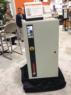
A POU unit is usually located at the end of the PLB. The POU unit receives 480V AC, 60 Hz power and converts it to 200/115V AC, 400 Htz power. In the United States and Canada, the POU is typically a Solid State Frequency Converter (SSFC). In countries with 50 Hz utility power, however, small motor-generator sets are also used. The current generation of POU units have software-controlled voltage drop compensation to try to ensure that the aircraft receives the voltage it requires. How successful the LDC of the gate box or the VDC of the POU units are depends on the cable length, the aircraft load and the power factor of the aircraft load.
The central power plant takes utility power and converts it to high voltage (575 V AC) 400 Hz power using paralleled motor generator sets or SSFC units. This high voltage 400 Hz power is then distributed to a gate box near the end of each PLB. The gate box drops the voltage level of the 400 Hz power from 575/332V AC to 200/115V AC that the aircraft requires. Usually, it also has a Line Drop Compensator (LDC) to try to handle the voltage drop that occurs in each phase of the output cable to ensure that the voltage that the aircraft receives is within its tolerance level of 115 ± 3 VAC and the voltage between phases is within 2V AC of each other. Depending on the manufacturer of the LDC, the maximum voltage boost is between 14 percent and 24 percent.
Historically, commercial aircraft required a mix of resistive and reactive current to power the aircraft while it was at a PLB/gate. The ratio of the resistive to reactive power is known as the power factor (PF) and for legacy aircraft it has been accepted as being 0.8. Now the next generation “all electric” aircraft have a power factor that is almost 1.0 (all resistive). This increase in the power factor has two major effects on the power that the airport needs to provide to the next generation of aircraft.
NEXT GENERATION
The first is that these aircraft require 25 percent more “useful” power than the legacy aircraft do. So as more gates are upgraded to support the next generation aircraft, the airport has to be sure that it has enough available power. The airport also has to be sure that all of the existing wiring and protective devices are still properly sized for the increased power requirements.
The second effect of the 1.0 power factor has to do with how the LDC works. Essentially, the LDC adds capacitance to counteract the inductance that is created in the cable at 400 Hertz and 0.8 PF. The larger the load on each wire in the cable and the longer the cable is, the greater the voltage drop will be. So, when an LDC is first installed, each phase is adjusted for a particular load and cable length at a power factor of 0.8. The problem is that as the power factor approaches 1.0 the inductance in the cable becomes negligible and then the induced capacitance has a negative effect on the voltage to the aircraft.
For LDC equipped gates, when the cable lengths are short and/or the loads are small (less than 40 kW) the voltage drops are usually within the voltage tolerance of the aircraft. However, when there are larger loads and/or longer cables (over 60 feet), which is typical for the B787, A350 and A380, an LDC equipped gate probably won’t be able to keep the voltage within the required aircraft voltage tolerances.
Most POU units constantly measure the voltage and current they are supplying to the aircraft and if they are correctly set up, boost the voltage as the current increases. This voltage boost is typically between 3 percent and 8 percent depending on the manufacturer. Also, the legacy POU/SSFC units can only adjust the inverter voltage and thus they have minimal effect on the phase-to-phase voltages. The newest generation of SSFC units (such as the AXA/Hobart 2400 units) can be calibrated to individually adjust each phase to maintain the required tolerances between phases and the overall voltage no matter what the power factor of the aircraft is.
Since almost all gates at an airport support a mix of aircraft, it is very unlikely that a gate will be dedicated to any of the next generation aircraft. Thus, the power requirements need to be carefully considered when a next generation aircraft is going to be assigned to a gate. Ensuring that adequate power at the correct voltage will be available to any aircraft that arrives at a gate can best be done by an SSFC POU unit that actively compensates each phase independently.
About the Author: Mark Frink is sales engineer for Hobart Ground Power - ITW GSE Group. He is responsible for engineering support to the company's sales force and customers of utility and diesel-powered PCA units, 400 Hz frequency converters and 28V DC power supplies.


