With many different methods of nondestructive testing (NDT), it’s important to know the difference between them and how each method works in an inspection.
Roger Engelbart, a member of the American Society for Nondestructive Testing board of directors, says the primary methods are: eddy current testing (ET), magnetic particle testing (MT), penetrant testing (PT), radiography testing (RT), ultrasonic testing (UT), and visual testing (VT).
“VT is not included in the specification for training and certification in NDT but is an important process in aviation maintenance,” continued Engelbart.
Engelbart explains the difference between each NDT method:
Eddy Current
Eddy currents are electrical currents within a conductor that are induced by a nearby alternating magnetic field. To produce eddy currents and employ eddy current testing, an alternating electrical current (AC) is driven through a test coil. This current produces a magnetic field perpendicular to the current's flow. By causing this magnetic field to interact with a conductor, by placing the test coil and test piece in close proximity, eddy currents are induced in the secondary conductor.
“The eddy current forms its own magnetic field, of opposite direction to the primary field, which interferes with the primary field. The interaction between the two magnetic fields causes impedance changes in the primary coil. The impedance changes are displayed on a screen for interpretation by an experienced technician or engineer,” described Engelbart.
A surface crack is detected by a rapid change in instrument response as the eddy current probe moves across the crack. The rapid response change results from a localized disruption of the eddy current and its secondary magnetic field due to the crack. The disruption of the secondary magnetic field induces a momentary change in coil impedance. A change in coil impedance alters the current through the coil, which is indicated by a change in instrument response.
“Eddy current is impacted by the loss of conducting material and a reduced secondary magnetic field by such features as curvature, reduced thickness, and proximity to edges,” Engelbart said.
Magnetic Particle
Magnetic particle testing can locate surface and near surface discontinuities in a variety of ferromagnetic product forms. This is accomplished by establishing a magnetic field within a part using electrical current, then applying magnetic particles to the surface while observing the particles’ behavior. When a discontinuity such as a crack in ferromagnetic material is encountered by lines of force, they attempt to stay within the material. Since the lines of force never touch, they tend to go under or around discontinuities.
“However, it is only when a sufficiently strong magnetic field has been applied that the lines of force are increased in number until they are forced out into the air. The magnetic leakage field (bridge) that is formed in the air attracts the magnetic particles and the accumulation of these particles makes the discontinuity more readily visible,” Engelbart said.
Subsurface discontinuities may be detected if they are large enough and the magnetic field generated is strong enough to cause a flux leakage. The applied particles may be in the form of a colored dry powder or fluorescent particles in a liquid carrier.
Penetrant Testing
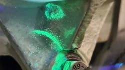
Liquid penetrant testing detects surface breaking indications such as pores and cracks and includes two types of dye: fluorescent and visible. Fluorescent dye is used almost exclusively for most aerospace applications, as visible dye has insufficient sensitivity. The penetrating liquid dye is applied to the surface of a part that has been thoroughly cleaned and dried; the time that is allowed for penetration is called dwell time. After the excess dye is removed from the surface, dye that was trapped in the cracks is drawn to the surface, usually by use of a developer, revealing the cracks.
“PT is the easiest and least expensive method to use. It is typically used on nonferrous metals but may be used on ferrous alloys as well. It requires a surface that is free of coatings, dirt, and contamination. If the surface has received any abrasive treatment, it must be treated with an acid etch to remove any smeared metal that would close off surface-breaking flaws,” he said.
Radiography
Radiography uses the principles of photon absorption as the basis for performing examinations. When x-rays are directed into an object, some of the photons interact with the particles of the matter and their energy can be absorbed or scattered. Other photons travel completely through the object without interacting with any of the material's particles. The number of photons transmitted through a material depends on the thickness, density and atomic number of the material, and the energy of the individual photons.
“The transmitted photons interact with radiographic film to produce a photo-like image of the object under examination. Radiography may also be performed with non-film imaging. Computed radiography (CR) uses a storage phosphor imaging plate in place of the film; digital radiography (DR) utilizes a digital detector array in place of the film or the phosphor plate. The availability of an electronic image allows some adjustments to be made to the quality of the radiographic image without repeating the exposure,” Engelbart said.
Radiography is used less often than other methods in aviation maintenance due to the need for strict radiation safety protocols when performing a portable on-aircraft examination, he noted.
“Radiography will not detect planar discontinuities such as delaminations in composites; it is useful for core damage in honeycomb structures. It can also be effective for crack detection, but the x-ray beam must be correctly aligned with the suspected crack location to obtain the best possible image,” Engelbart said.
Ultrasonic
“Ultrasonics operates by sending high-frequency sound (above 20 kHz) through a part. The method functions in two modes: through-transmission ultrasound (TTU) and pulse echo (PE). TTU requires access to two opposite faces of a structure, and that structure must have no designed air gaps between those accessible surfaces,” Engelbart said.
TTU works by sending a stream of ultrasonic pulses from a transmitting transducer located on one side of the structure, through the structure to be detected by a receiving transducer on the opposite side. TTU shows the location of a discontinuity but provides no information on its depth. Single-sided, or PE ultrasonic examination, uses a single transducer positioned on one side of the structure to transmit and receive sound. Unlike TTU, PE will provide depth information for a discontinuity.
“Much of the use of ultrasonics in aviation maintenance is in the PE mode, as it can be accomplished with portable equipment. Ultrasound does not penetrate air and the method depends on a coupling medium such as water, oil, or a light gel between the transducer and the surface of the structure to be examined,” he explained.
Visual Examination
Visual examination is the most basic method of NDT and is capable of finding a number of discontinuity types in both composite and metallic structures. Engelbart notes the keys to a good visual examination are the following:
- Adequate Lighting
- Magnification
- Accessibility/Orientation
- Examiner visual acuity and patience
“The unaided eye is usually the first approach used in visual inspection; this is especially true for in-service damage assessments during which a complete walk-around of the aircraft is the initial procedure. General visual inspection utilizes such aids as magnifiers, mirrors, hand measurement tools, and borescopes. Magnifying instruments may be useful in distinguishing fine features; some magnifiers may have a measuring lens attached, while in other cases a supplemental scale might need to be placed in the field of view to assist in determination of an approximates size of a condition,” he continued.
Adequate lighting may be achieved by locally illuminating the region of interest with a supplemental light source. Uniform lighting is strongly recommended; however, circumstances may limit light sources to flashlights, or floodlights. Light angle and viewing angle may also improve evaluation of the inspection region. This is especially true for metallic structures where surface reflectivity may be a factor in the quality and accuracy of the visual assessment.
“For interior structures and areas with limited access, a remote visual imaging (RVI) system may be needed – borescope, fiberscope, or video image scope that provides the image to be viewed on a video monitor,” Engelbart said.
When to Use Each
Unless there’s specific damage location that is already known, the process begins with a visual walk around of the aircraft, looking indications of potential damage, said Engelbart.
“The first indication is the condition of the paint – chipping, cracking, indentation due to impact, or discoloration due to overheating,” he said. “Any of these indications prompts a closer visual examination to determine if there is a likelihood of subsurface or internal damage.”
Below is a list of defect/damage types and circumstances for each method:
ET – surface and shallow subsurface cracks in metallic structures, and metal loss due to corrosion.
MT – cracks in landing gear components.
PT – surface breaking cracks in metal structures due to impact.
RT – fractures of internal structural members, damage to honeycomb core in sandwich structures.
UT – disbands due to failed adhesive bonding (metal or composite), and delaminations of composites due to impact.
About the Author

Walker Jaroch
Editor
Contact: Walker Jaroch
Editor | AMT
+1-920-568-8399
>> To download the AviationPros media kits, visit: Marketing Resource Center
>>Check out our aviation magazines: Ground Support Worldwide | Airport Business | Aircraft Maintenance Technology