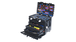
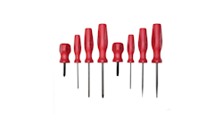
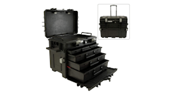
We all know the challenges involved with justifying the purchase of additional or specialized tooling, particularly if the tooling is not a high-use item. How often have we heard comments like, we don’t want to spend the capital to purchase this special tooling. We may only need it a few times. Often times this is followed by, as a result of not buying the correct tool we now have to make a repair to the item. And of course the most popular phrase among aircraft technicians has to be the phrase, the right tool for the right job.
Improvising when it comes to special-use tooling is commonplace in aircraft maintenance, and many times this works well. Aircraft mechanics are resourceful and take pride in crafting their own special tools. How many of us have used sockets and a bench vise to force a worn bearing from its housing, and then use the same innovative method to install the new replacement?
Proper bearing installation is a critical task which has a high cost in both time and materials and has become a major focus and concern of the prime airframe manufacturers. Proper bearing installation can affect both aircraft performance and safety, and for technicians and maintenance organizations deserves a second thought before your improvised tooling causes damage resulting in further repairs.
To learn more about the basic function of a bearing and proper removal and installation I turned to Scott King principle with King Industries. King began by saying, “First, think of a bearing as the sacrificial part of any mechanical system. A bearing is designed to see wear, it will wear, and it is designed to eventually be replaced so that other major components in the system do not need to be replaced.”
According to King you can generally place bearings into two primary groups. The first type of bearing provides rotational ability for a part in a system and reduces friction created by a full rolling element. These bearings are considered rotational, they are subject to high radial loads, and are generally secured in a housing using a staking method that displaces housing material over a chamfer in the outer race of the bearing. This can be accomplished by either rolling the housing over the bearing or staking the housing with a ball or line impression.
The second primary use of bearings in aircraft is for positioning of attaching components, such as a movable flight control like an aircraft rudder. These bearings are not rotational and subject to higher lateral loads. They are secured into place by either swaging a groove that is in the outer race of the bearing into a chamfer in the housing, or swaging a sleeve into the chamfer on the bearing and in the housing.
Removing and installing a swaged in place bearing
King says, “Many times proper tools for bearing removal are overlooked. Weakening the lip by cutting is critical.” When removing a grooved bearing that has been swaged in place, the lip must be weakened in order to remove it and press out the old bearing. Care must be taken to ensure the cutter doesn’t damage the housing, and that the old bearing does not scratch the housing when being pressed out of place.
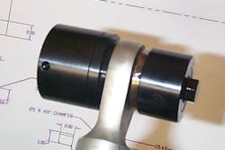
Weakening the sleeve or lip in order to remove the bearing can be done in several ways; grinding or machining the swaged lip; using a drill press or milling machine with a hole-saw style cutting tool; or using a hole-saw style portable cutting tool. Using the portable tool is the preferred method as it provides access to the component on the aircraft, and more importantly it ensures proper alignment of the cutter so it does not damage the housing during the cutting process.
At this point the bearing is ready to be pressed out of the housing using a removal tool. The proper removal tool should be of a size and design that ensures the cut lip does not scratch or damage the internal surface of the housing bore when pushing the bearing out.
Cleaning, inspecting, and bearing installation
Once the housing bore has been cleaned and inspected in accordance with the aircraft maintenance manual the new bearing is ready to be installed. The installation tool must push on the bearing at a specific location that does not damage the bearing when installing it into the housing. This is generally accomplished with the same tool as used to remove the old bearing, making sure the bearing is pressed into the housing parallel to the bore in the housing so it is not cantered in the housing.
“If the bearing is installed at even a slight canter you risk damaging the housing," King says. "Once the bearing is pressed into the housing it needs to be located correctly in the housing bore. Using the proper installation tool ensures this alignment and location is correct.” At this point the bearing is ready to be secured in place by swaging the bearing lip or sleeve.
There are several methods used when swaging the bearing or sleeve; the anvil method; two-wheel roller method; and tri-roller method. The anvil is a piece of metal machined at an angle that under high pressure forms the lip into the housing chamfer. This method is typically used in high production applications.
The two-wheel roller rolls the lip into the chamfer. But care must be taken as this method has a tendency to gall the lip if the wheels skid. The nature of the two-wheel rollers are to roll straight and not in a circular manner. The tri-roller also rolls the bearing lip into the housing chamfer. According to King, the tri-roller wheels actually roll around the lip providing a superior and nondamaging swage and this has become the preferred method for bearing swaging.
Final inspection and testing
Once the bearing has been properly installed visually, inspect the lip for cracks in the swage or excessive galling caused by the installation. In either case the integrity of the lip may be degraded and proper holding force compromised. In addition to a visual inspection there are a few common types of testing methods used to ensure the bearing installation has not adversely affected the operation or rotation of the new bearing: proof load testing and breakaway torque.
Proof load testing is used to ensure the new bearing will handle the lateral forces it sees in service; a check of the installation itself. Proof load testing is typically done according to a process specification, referencing an engineering drawing, or other approved maintenance data.
Breakaway torque is used to ensure the bearing turns or rotates correctly, and has not been loaded or squeezed during the installation process. King says, “Properly testing both the load and torque measurements accurately without damaging the bearing also requires specific tooling.”
Conclusion
“The effects of improper bearing removal and installation can result in many things from damaged housings to premature bearing wear," King concludes. "The importance of proper tooling used when removing and installing bearings is often times over looked. Incorrect bearing installations will create friction and transmit higher forces throughout the system. This can result in fatigue and premature wear not only on the bearing but other components in the system. Eventually this wear can cause vibration throughout the aircraft, the same type vibration that you were attempting to eliminate by replacing worn bearings.”
For more information on bearing removal and installation tooling contact King Industries at (888) 549-KING (5464) or visit www.stakingindustries.com. King Industries bearing removal, installation and testing tooling can also be found distributed by Snap-on Industrial.
