Magnetos: Installation Tips
The magneto is a completely self- contained ignition device. Magnetos have been around since the early 1900s and have been refined for the last 100 years to give us the reliability we have come to expect from aircraft magnetos. As maintenance professionals, it is important that we understand what makes a magneto tick. In this article, we will discuss magneto theory of operation as well as items necessary to prepare a magneto for installation.
Theory of Operation
Changes in magnetic fields produce electricity. The faster the magnetic field changes the more electricity is produced. The spinning motion of the magnetized rotor induces a small voltage of less than 100 volts in the primary windings of the coil. This voltage makes the iron core in the center of the coil become an electromagnet, just like wrapping a nail with copper wire and attaching it to a battery like we did as children.
The rotor only spins fast enough to produce about 100 volts in the primary windings of the coil, not nearly enough to fire a spark plug. In order to boost that voltage to above 14,000 volts, we use two integral parts of the magneto.
Remember we mentioned that how fast we change the magnetic field is directly related to voltage output. If we can instantly turn off the voltage flowing through the primary coil windings there will be a much higher voltage output. The way we “unplug” that voltage in the primary windings of the coil is by opening the breaker points in the magneto. This instantly collapses the magnetic field that we have built up in the iron core of the coil. This is the first method to boost the voltage.
The second way we boost the voltage is by means of a secondary coil. Wrapped around the primary coil windings are about 100 times as many secondary coil windings. The instantaneous collapse of the magnetic field by opening the points creates a very high voltage in the secondary windings of the coil. This is the voltage that fires the spark plugs.
The Capacitor
It takes about 8,000 to 12,000 volts to jump a spark plug gap. However, if two pieces of metal are touching and then moved apart, like the magneto contact points, it takes less than 20 volts to jump the resulting gap.
If voltage was allowed to jump the points gap, our magnetic field would collapse much more slowly and greatly reduce our output voltage as well as quickly erode the faces of the points. So, the capacitor acts like a sponge soaking up the 100 or so volts from the primary coil, until the points are far enough apart to prevent the current from jumping across the point gap. If the capacitor has failed, it will result in a high magneto drop, and severe point erosion. Accurate capacitor testing equipment is complex and expensive.
Preparing Magneto for Installation
Let’s get back to the basics. Most IAs have probably nstalled a number of magnetos. However if you deal primarily with turbine or jet engines this process may not be familiar.
More than twice as many magnetos are returned to the factory due to incorrect installation than all of the other warranty claims combined. When troubleshooting an ignition problem, verify at least twice that the magetos are installed correctly. A second set of eyes is always helpful in these situations. In hopes of eliminating some of these installation issues, let’s review the basics of installing a Slick magneto.
First, let’s install the magneto driver or drive gear from the old mags onto the new mags and torque the nut to 120 to 320 inch pounds. Use the supplied cotter pin to secure the castellated nut with the long leg up toward the end of the shaft. On impulse coupling magnetos, there should be .010 to .020 inch end play on the gear. This is normal and not a reason for concern.
Next, prepare the magneto for installation by setting the mag to fire the No. 1 cylinder. All Slick magnetos that were manufactured in the last 25 years use a small pin that is inserted through the distributor block and through a corresponding hole in the distributor gear. When the pin is installed correctly, the magneto is ready to be installed on the aircraft.
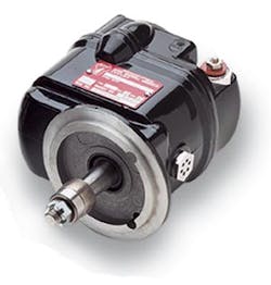
First, remove the white plastic distributor cover and save the screws. Install the T-116 timing pin into the hole on the distributor block marked “L” or “R” depending on the rotation of the mag. Look at the magneto data plate to determine the direction of rotation as pictured in the photo on the opposite page.
It does not matter which direction your engine turns — look at the magneto data plate to determine where to put the pin.
That Darn Pin
The pin has to be inserted in the correct hole and inserted completely or the mag just will not work. In order to accomplish this, turn the magneto input shaft to align the pin hole in the distributor block and distributor gear. Impulse coupling magnetos should be turned backwards to prevent any tension from building up on the impulse coupling spring when the pin is installed.
There is an electrode between the distributor block and the distributor gear that may contact the timing pin when you are trying to install it. Do not be fooled by this electrode. You may need to lift the pin out about ¼ inch while you continue to turn the magneto shaft where it clears that electrode just enough to put the pin down and get it fully seated. Make sure the pin is fully seated. The pin will go all the way down to the first shoulder when correctly installed.
Preparing the Engine
I don’t know how many times I’ve heard of magnetos being installed on top dead center of the exhaust stroke, and the mechanics swear on a stack of bibles that it is on the compression stroke. Don’t tell anyone, but I’ve done it myself. Here’s how to verify that the engine is ready.
First, remove the top spark plugs from all of the cylinders. Then, turn the propeller in the normal direction of rotation with your thumb over the spark plug hole on the No. 1 cylinder. When the air pressure on the No. 1 cylinder starts to build up and tries to blow your thumb off the hole, slowly continue to turn the prop until the timing mark listed on the engine data plate lines up exactly with the split line on the top of the crankcase for Lycoming engines or the split line on the bottom of the crankcase for Continental engines. Typically, Lycoming engine timing marks are located on the starter ring gear and Continental engine timing marks are located on the propeller flange. A degree wheel is highly recommended on Continental engines. I spent six months in the assembly room at Teledyne Continental Motors. During that time these professional assemblers never once installed a magneto without using a degree wheel. It would be pretty arrogant for a mechanic that installs a magneto once or twice a month to assume that he or she could accurately install a magneto on a Continental engine without using a degree wheel.
The engine will be on the compression stroke of the No. 1 cylinder, and you are now ready to install the magneto.